
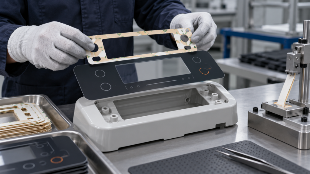
What must be specified and validated before approving die-cut tape for a printed appliance control-panel overlay?
Identify the complete overlay and housing interfaces, lock one grade and die-cut design, then pass a representative process trial against OEM-defined appearance, retention and functional criteria.
figures and test-method references in this guide are for preliminary selection only. Final performance depends on the exact construction, thickness, substrate, application and test method; request the report for the proposed grade before approval.
A double-sided tape can be considered for bonding a printed appliance control-panel overlay to its housing, but a product-family label cannot approve the assembly. The OEM should release a die-cut construction only after the exact overlay print stack, housing finish, bond geometry and production application have been represented in a controlled sample trial. Identify the complete overlay and housing interfaces, lock one grade and die-cut design, then pass a representative process trial against OEM-defined appearance, retention and functional criteria. The decision is whether the proposed grade and process meet the buyer’s appearance, retention and environmental criteria—not whether PET carrier tape is generally used in appliances. In an appliance control-panel overlay tape project, begin by naming the exact printed control-panel overlay layer and housing surface that the adhesive must join.
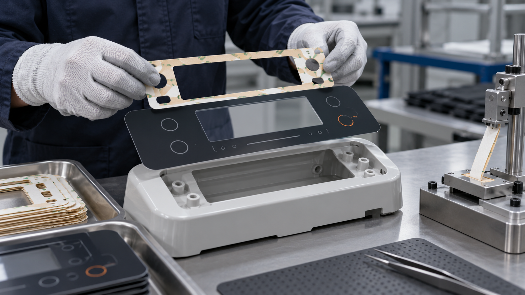
This guide is limited to pressure-sensitive bonding of a printed control-panel overlay to an appliance housing. It does not qualify a membrane switch electrically, seal a PE-foam panel joint, or establish a LubandArt grade’s compliance with an appliance standard. The current LubandArt PET tape product page describes a candidate product family and confirms that construction and dimensions are project-specific. The exact adhesive, overlay stack and housing interface still need confirmation.
Start with the actual overlay stack and housing surface
An “overlay” can mean different constructions. It may be a printed polycarbonate or polyester film, a graphic layer laminated to another film, or a control surface that includes a membrane-switch circuit. Document the full stack from the visible face to the adhesive side: film type and thickness, print location, ink or coating, hard coat, primer, backside treatment and any laminate. Identify which layer the tape will touch. A tape bonded to a print varnish is not automatically equivalent to one bonded to bare film.
Describe the housing side just as specifically. Record whether it is painted metal, powder-coated steel, aluminum, ABS, PC/ABS or another material; include the coating or surface treatment, texture, cure, molding-release concerns and cleaning method. If the housing has ribs, recesses or a curved bezel, capture the dimensions and tolerance. A flat lab coupon can screen an adhesive, but a coupon made from a different resin or coating cannot establish production adhesion to the real housing.
The first approval gate is a defined interface pair. If either side’s composition or finish is unknown, keep the construction at candidate status. Ask the overlay converter and housing supplier for material identification and revision control before the tape supplier recommends a grade.
Choose construction after defining what it must hold
A double-coated PET tape uses a film carrier between adhesive layers; an adhesive-transfer tape has no carrier film. Those are different constructions. A carrier may help a converter handle and die-cut a thin component, while a carrier-free adhesive may suit a different lamination geometry. Neither is universally preferable. The die-cut part’s size, narrow lands, internal openings, registration tolerance, liner release and application equipment determine which format can be processed reliably.
The load case matters as much as the material name. State overlay dimensions, bonded perimeter or area, unsupported spans, curvature, orientation, expected press or touch loads, and any tendency for edges to be lifted during cleaning or servicing. Note whether the overlay is decorative only or carries a functional control interface. If it includes switches or conductive traces, the tape layout must avoid blocking active zones, changing switch travel, interfering with vents, or covering grounding and connector features. Electrical and tactile performance need their own acceptance checks; a bond-only peel test cannot establish them.
LubandArt’s PET tape product page lists PET-carrier tape as a customizable family for precision die-cutting and appliance applications. 3M lists graphic overlay and membrane-switch bonding as examples for its own 200MP transfer-tape family; that confirms an industry use case, not LubandArt grade suitability. That makes it a relevant route for a sourcing discussion, not evidence that a particular grade bonds the buyer’s print coating or housing finish. Request a proposed grade and revision, adhesive system, total thickness, liner, die-cut drawing and any available grade-specific report. Keep each item tied to the sample and quote.
Control converting and application
A well-selected adhesive can still fail if the die-cut part is difficult to place or the application process varies. Define the part outline, cut tolerances, liner construction, tabs or split liners, winding orientation and whether the part arrives as individual pieces, sheets or a roll. Check that the liner releases without stretching the overlay or lifting narrow adhesive features. For automation, confirm the feed direction, pick-and-place method, registration datum, peel plate and allowable cycle time.
At application, record surface preparation, room and part temperature, pressure or roller/fixture, application sequence and delay before the assembly is loaded or tested. 3M technical information for its own PET and transfer-tape products notes that surface contact, cleanliness, dryness and application pressure affect bond development. The 3M 6012 application techniques are product-specific; use them only to identify variables to control, not as another supplier’s process specification. Use that only as a reminder to control these variables; do not apply 3M product values or instructions as LubandArt specifications. Follow the proposed grade’s own technical instructions and safety documentation.
If the OEM process requires an adhesive to withstand a later paint bake, elevated-temperature assembly, cleaning chemical or humidity exposure, write down the actual profile and duration. “High temperature” or “appliance use” is not a test condition. Short exposure during manufacturing and long-term service conditions are separate requirements and should not be collapsed into one pass/fail claim.
Build a representative sample trial around failure modes
A useful trial compares candidates on production-representative overlay and housing materials. Identify each sample by grade, revision, lot and die-cut revision. Record substrate suppliers and finishes, cleaning procedure, application pressure, placement, dwell before evaluation and environmental conditioning. Keep a control sample if possible. Photograph the assembly before and after conditioning so edge lift, bubbles, print damage and adhesive transfer can be reviewed consistently.
Set acceptance criteria before testing. Depending on function, the OEM may check visual alignment, edge lift, bubbles, adhesive squeeze-out, overlay movement, removal damage, switch actuation, legibility after cleaning, and retention after relevant temperature or humidity exposure. Use the buyer’s specified method and limits. If peel or shear testing is used, record specimen geometry, test direction, speed, dwell, conditioning and failure mode. A test number without its method and substrate does not explain whether the design is acceptable.
Separate screening from release. A small coupon trial can eliminate clearly unsuitable candidates. Final release should include the real die-cut geometry and normal assembly process, with enough samples to capture expected process variation. If a trial fails, identify whether the interface separated, adhesive split, the overlay distorted, print was damaged or the part was misapplied. That observation helps select the next controlled change; it does not by itself prove root cause.
Keep overlay, switch and gasket decisions separate
Some supplier literature discusses graphic overlays and membrane switches together. The terms overlap in the market, but engineering requirements may not. A decorative overlay bonded to a rigid fascia is primarily a surface and retention problem. A membrane switch also has circuit layers, spacer geometry, actuation force, contact closure, tail routing and electrical checks. A single tape trial should not approve both functions unless the test plan explicitly covers them.
Likewise, a control-panel tape joint is not the same as a foam gasket around an appliance panel. A gasket may need compression recovery, gap filling and ingress testing; a thin overlay bond usually has different thickness and appearance constraints. Keep these decisions on separate drawings and specifications so a successful result for one interface is not overgeneralized to another.
Make the approval record repeatable
Before production approval, the sourcing file should contain the exact tape grade and revision, sample or lot reference, overlay and housing material revisions, die-cut drawing, application settings, test method, conditioning and buyer acceptance results. Agree which changes trigger review: adhesive formulation, carrier, thickness, liner, coating, converting tool, substrate finish or application equipment. Define who signs off when a change affects the qualified interface.
The practical decision is straightforward: approve a die-cut tape only when the proposed construction and controlled process pass on the real overlay stack and housing finish against requirements set by the OEM. If the supplier can offer only a family description, or if the test uses substitute materials, the tape remains a candidate. Send the overlay cross-section, housing material and finish, part drawing, application sequence, service profile and required acceptance tests with the RFQ. That gives the supplier enough information to propose a sample without implying that an untested grade is already approved. See the PET film versus paper liner guide for the related converting decision, and use the contact page to submit project conditions.
Frequently Asked Questions
Does a PET tape product page prove that a grade will bond my overlay?
No. A family page identifies a route for evaluation. Compatibility depends on the actual print-side layer, housing finish, grade, die-cut geometry and process trial.
Is a control-panel overlay the same as a membrane switch?
Not always. A membrane switch adds circuit, spacer, actuation and electrical requirements that need separate checks beyond adhesion and appearance.
What should I send with a sample request?
Send the overlay cross-section, print and coating details, housing resin or finish, drawing, application sequence, service profile and acceptance criteria.
Send the overlay stack, housing surface, die-cut drawing, process sequence and buyer acceptance criteria for a proposed sample construction.
Request a quote · [email protected] · WhatsApp +86 180 6469 2463
Need this construction for a production run?
Get a quote