
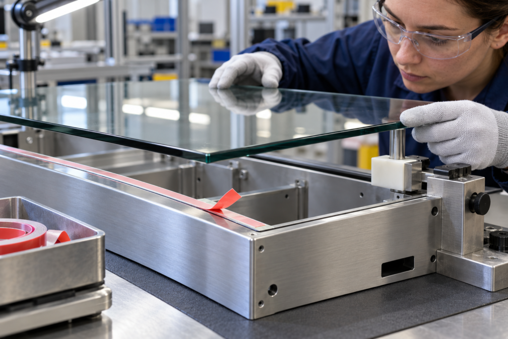
figures and test-method references in this guide are for preliminary selection only. Final performance depends on the exact construction, thickness, substrate, application and test method; request the report for the proposed grade before approval.
A glass-to-metal panel assembly should be designed around its function, interfaces, bondline geometry and service conditions. A double-sided tape can be a candidate for a non-structural industrial panel, but the material pair alone does not qualify a grade. Compare acrylic foam and thinner film-carrier constructions against the required bondline, flatness, tolerance and appearance, then qualify the exact grade on representative parts before release. For procurement, “double sided tape for glass and metal” is only an entry point; it does not specify the carrier, bondline or test for the buyer’s assembly.
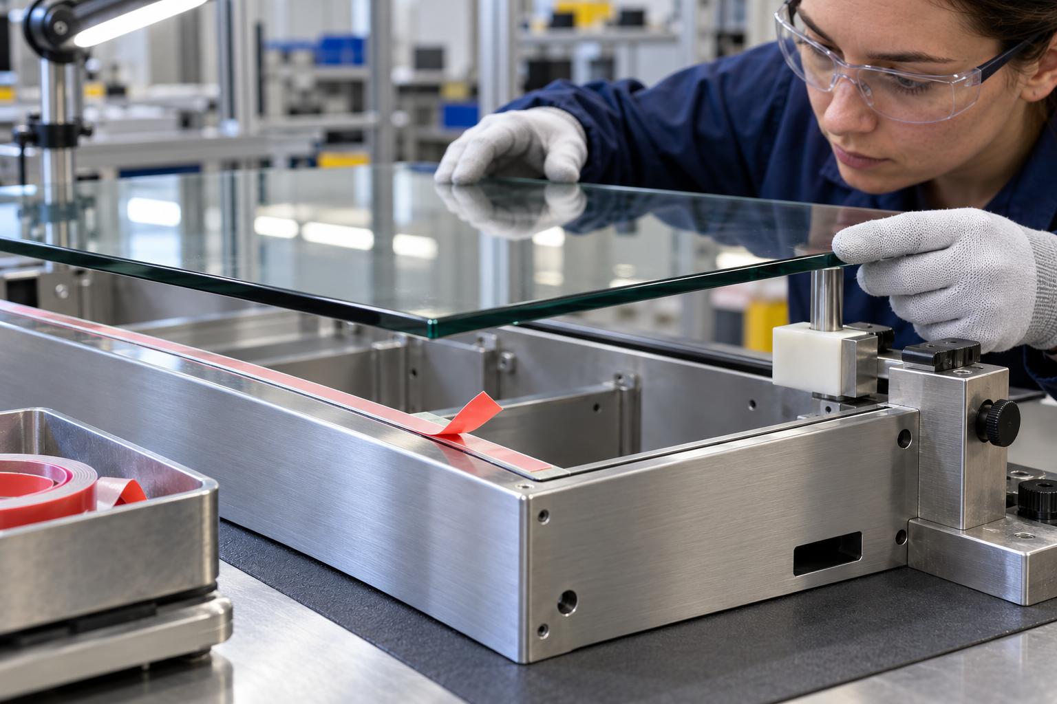
Start with the job of the joint, not the tape family
Before comparing tape constructions, write down what the glass panel must do in the assembly. It may be a cover, display window, decorative face, viewing panel or protective layer. Identify whether the joint carries only the panel’s own weight, sees handling or vibration, contributes to a seal, or must meet a defined retention requirement. These functions can exist together, but they should not be collapsed into a vague requirement such as “strong bond.”
Also define the consequence of failure. A panel that shifts cosmetically may have a different disposition from a panel that exposes electronics, loses a fluid seal or creates a personnel hazard. Structural glazing and safety-critical joints require an application-specific engineered system, applicable approvals and a defined test program. If the assembly is part of a façade, overhead glazing, a vehicle system or another regulated construction, follow the qualified system and engineering process required for that application. A general-purpose industrial tape selection guide cannot establish structural glazing approval.
LubandArt lists glass and metal among possible substrate families on its acrylic foam tape page, and says final construction suitability is confirmed against the project specification and a sample test. The foam tape product page identifies a candidate route, not grade approval. That supports discussing a candidate, not approving a particular grade. A double-sided PET tape route is another product-family option; the PET tape page also does not establish a glass-to-metal qualification. Keep the decision tied to the selected product, surfaces and assembly.
Choose foam or film from the bondline geometry
A foam carrier can be considered when the joint needs some compliance to accommodate surface variation, part tolerances or a designed bondline. Its thickness and compression behavior influence the gap, edge appearance and how the panel sits relative to the frame. “More foam” is not automatically safer: a thicker layer may change panel position, increase visible edge, alter stiffness or create an unacceptable cosmetic step.
A thin film carrier may suit a flat, smooth joint where low profile and dimensional stability matter more than gap accommodation. tesa describes its double-sided film-tape category as intended for flat, smooth surfaces such as glass and metal (see tesa’s category page). That is a construction-class example from tesa, not a recommendation for a LubandArt grade. The selected adhesive still has to bond to the exact surfaces and survive the intended environment.
Compare part flatness, gap, tolerance, movement and edge appearance against the exact carrier and thickness, then check contact across the full bond land on representative parts. Compare the actual carrier, adhesive on each face, total thickness, liner, width and converting format against the mating surfaces, allowed bondline, part tolerance, edge visibility, assembly pressure and downstream operations. If the glass or metal is not flat, or the frame has local steps, ask whether the proposed geometry maintains contact across the complete designed area. A material-family label cannot answer that without a drawing and sample.
Identify the actual glass and metal surfaces
“Glass” and “metal” are not complete substrate descriptions. On the glass side, record whether the adhesive contacts bare glass, a ceramic frit, printed border, coating, film or treated surface. Confirm which face is bonded and whether cleaning, handling or an upstream process can leave residue. If a coating or printed layer is the interface, qualify that surface rather than treating it as bare glass.
On the metal side, identify the alloy or component specification where known and the finish that actually contacts the tape: painted or powder-coated steel, anodized aluminum, conversion coating, plated material or another treatment. Record whether the finish is fully cured, its texture and any process oils or release agents. A coating-to-adhesive interface can be the limiting bond even when the metal itself is easy to identify.
Use production parts whenever practical. If the sample uses polished glass and a clean metal coupon but production uses a printed glass edge and powder-coated frame, state that difference in the test record. A successful result on a simplified coupon may help compare candidates, but it does not automatically qualify the production interface.
Set the bondline and load path before selecting width
Make a joint drawing that shows the tape path, width, edge clearance, corners, gaps, panel overlap and any openings or fasteners. Include the tolerance stack for both components. Decide how the panel is supported during application and what prevents it from sliding while the adhesive contacts the second surface. A narrow land, interrupted surface or sharp corner can concentrate stress at an edge.
Describe how forces reach the bond. Shear, peel and cleavage do not load a joint in the same way. Panel weight, vibration, impact during handling, thermal movement and pressure from a gasket or enclosure can change the stress pattern. For glass-to-metal assemblies, different thermal expansion and frame stiffness may move the edge over service cycles; the degree depends on the materials, dimensions and restraints. Treat this as a design variable for the specific assembly, not a universal tape property.
Set allowed panel movement, visible edge, gap, flatness and retention criteria from the product drawing or customer requirement. If the tape also seals, define the ingress test and assembly compression separately. Do not infer a water-ingress rating from closed-cell foam or from the fact that a tape is used on a glass panel.
Follow a controlled surface-preparation and assembly process
The 3M VHB design guide treats glass and metal surface preparation as material-specific design variables and labels its performance data as representative. These examples are useful for framing questions, not for transferring a 3M result to a LubandArt grade (see the 3M VHB design guide). Ask the supplier for preparation instructions for the proposed construction and confirm that the cleaner or treatment is compatible with the glass coating and metal finish.
Record glass coatings or prints, the metal finish, cleaning and handling, placement pressure, dwell, conditioning and sample criteria; follow the selected product’s instructions. Write the assembly sequence so another operator can reproduce it. Record the surface-cleaning method, wipe materials, drying time, tape application side, placement aid, liner-removal sequence, contact pressure or fixture, time between bonding steps and any conditioning before test. If the line is automated, include positioning tolerance, cycle time and equipment variation. Verify that the process does not scratch the visible surface, trap contamination or stretch the tape during placement.
If a primer or surface treatment is proposed, evaluate it as part of the complete system. Check its compatibility, flash or cure conditions, operator controls and effect on appearance. A treatment that improves adhesion on one coating may be unsuitable for a different finish. Change one controlled variable at a time during development so that a result can be connected to the surface, process or construction that produced it.
Build a representative qualification trial
Start with parts that match the intended glass face, coating, metal finish, bond geometry and assembly method. Identify the tape grade, lot, thickness, width and liner. Define sample count and conditioning based on the buyer’s requirement and the supplier’s product-specific instructions. Include the relevant service exposures—such as temperature cycling, humidity, water, vibration or handling—only where they represent the actual use case.
Agree the acceptance criteria before testing. Depending on the application, those may cover panel movement, edge lift, visible gap, appearance, retention, sealing or the result of a defined destructive check. Specify when and how each observation is recorded. Do not use an unrelated supplier’s published value as a pass limit for a different grade, substrate or joint.
Inspect failures by location and mode. An adhesive release from the glass coating, separation from the metal finish, cohesive split within the tape, edge lift, panel shift and damage to a coating point to different follow-up questions. None alone proves root cause. Record photographs, materials, preparation, application conditions, conditioning and test method so engineering can decide whether to change the interface, bondline, process or tape candidate.
Make the supplier review specific
A useful RFQ or sample request includes the glass type and bonded face, coating or print, metal and finish, joint drawing, bond land and tolerances, panel size and mass, load and service conditions, visible-edge requirement, assembly sequence and acceptance criteria. Ask the supplier to identify the exact construction, available product-specific reports and any assumptions that still require confirmation.
LubandArt’s acrylic foam tape page and PET tape product page provide candidate routes. The surface preparation and bond strength guide covers broader interface variables. None replaces a test on the selected grade and actual assembly. A candidate is ready for release only when the relevant engineering owner confirms that the tested construction and process meet the documented requirement.
Frequently Asked Questions
Does a glass-and-metal product route prove a tape grade is qualified?
No. A product-family page can identify a candidate route, but qualification depends on the exact glass face, metal finish, bond geometry, process and service conditions. Confirm these with representative samples and buyer-defined criteria.
Should I use acrylic foam or a thin film-carrier tape?
Compare the required bondline, surface flatness, tolerance, movement, appearance and assembly process. Foam and film are different construction families; the selected grade must be tested on the actual surfaces.
Can a general industrial tape guide qualify structural glazing?
No. Structural glazing and safety-critical assemblies require the application-specific engineered system, approvals and test program. This guide covers candidate screening for general industrial panel assemblies only.
Send a joint drawing, glass face/coating, metal alloy/finish, bond land, service conditions and target criteria to request candidate constructions and a representative sample plan.
Request a quote · [email protected] · WhatsApp +86 180 6469 2463
Need this construction for a production run?
Get a quote