
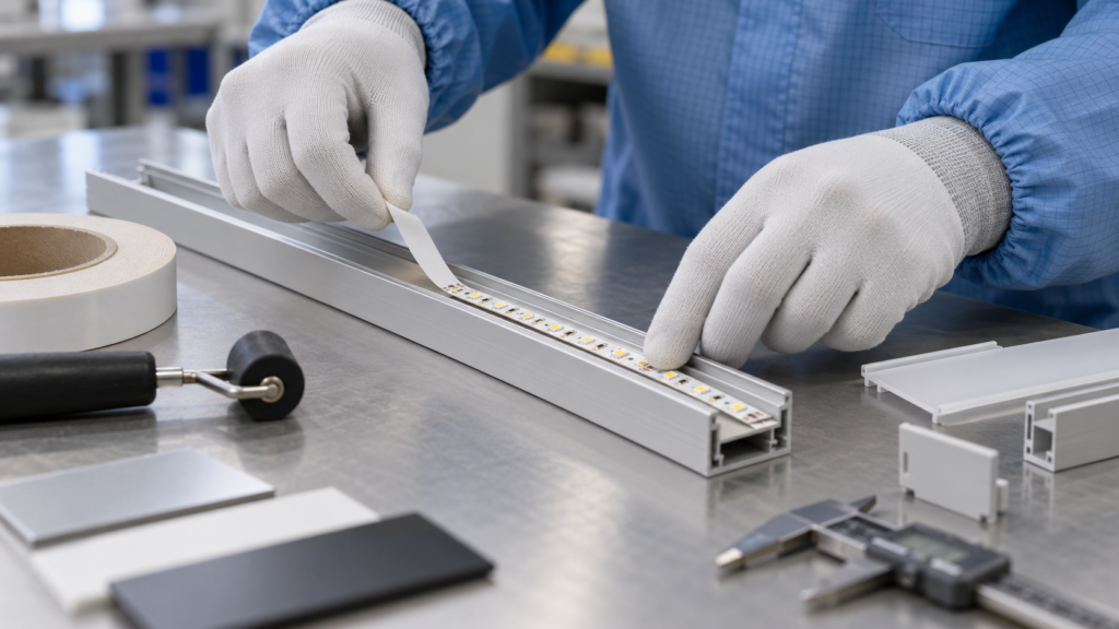
What must be specified and tested before approving double-sided tape to mount an LED strip PCB in an aluminum profile?
Identify both tape-contact surfaces and service conditions, then approve only a named construction and process that pass a representative trial; tape selection alone does not establish LED thermal performance.
This guide is for preliminary B2B selection. The cited tesa and 3M materials apply to their stated application context and named products only. No LubandArt grade is approved here. Thermal, electrical and optical acceptance remain with the product design authority and require testing on the proposed assembly.
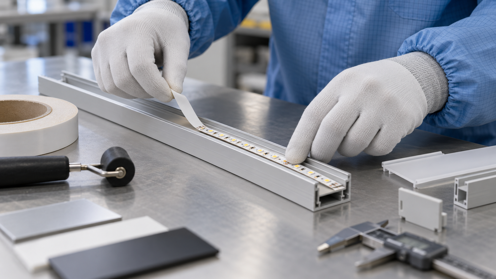
Define the two surfaces before asking for a tape grade
A double-sided tape can be a candidate for securing an LED strip PCB in an aluminum profile, but the application name does not identify the bond interfaces. The PCB underside may be a polymer coverlay, solder mask, protective coating, exposed circuit feature or a manufacturer-applied backing. The channel may be bare, anodized, painted or contaminated by machining and handling. Confirm exactly which layer the adhesive will touch on each side. Do not assume that “PCB” and “aluminum” are single, consistent substrates.
Record the LED strip manufacturer and revision, strip width, backing-layer description, surface finish and any release liner on the strip. On the profile, capture alloy if known, finish, extrusion revision, surface roughness or texture, cleaning method and whether a diffuser or cover changes how the strip is installed. If either supplier treats its surface or backing as proprietary, request a representative sample and written identification instead of guessing from appearance.
LubandArt’s PET tape product page describes a customizable product-family route for die-cut or converted components. Its public page does not approve an LED-strip grade, confirm adhesion to a particular PCB backing, or claim to manage LED heat. The buyer must qualify a specific construction against the actual materials and service conditions. For a buyer searching for double-sided tape for LED strip mounting, the decisive information is the exact pair of surfaces and the production test plan.
Decide what the tape joint is expected to do
Write the function of the bond in the assembly drawing. Is the tape only holding the strip in position during installation? Must it retain the PCB through vibration, thermal cycling, transport and the product’s full service life? Will it keep the strip flat against the channel, or is the channel’s geometry already providing mechanical capture? Clarify whether removal or replacement is allowed, and whether residue or damage is acceptable during service.
Map the bond geometry. Record the actual tape width, length, end gaps, corners, narrow lands and interruptions for connectors, solder joints or mounting clips. Check whether the channel has a flat bonding floor or a shallow radius. A continuous strip on a flat sample is not representative if production uses short segments, cutouts or a curved extrusion. Also note assembly orientation: a vertical profile or overhead installation can impose a different handling load before the adhesive has developed its intended bond.
Do not use the tape to solve a thermal-management problem by assumption. The aluminum profile, LED power, PCB design, thermal interface and airflow determine heat dissipation. Tape construction can change spacing and contact geometry, so the engineer responsible for thermal design should review the actual stack. Unless a proposed grade has product-specific thermal data and the assembled light passes its thermal acceptance test, describe the tape as an attachment layer only.
Compare constructions by the job they must perform
Double-coated PET tape has a film carrier between adhesive layers. A transfer tape has adhesive without a film carrier. A foam tape adds a compressible layer. Those constructions differ in handling, thickness, conformability and die-cut behavior; none is a universal choice for LED profiles. A stable carrier may help a converter make narrow or repeatable parts, while a softer layer may accommodate some surface variation but also change the spacing between PCB and channel. A transfer adhesive may fit a different lamination process. Choose only after checking geometry and required function. PET carrier tape is a construction description, not proof that the adhesive suits a particular PCB backing or profile finish.
The tesa profile brochure lists LED-strip mounting among profile applications. That confirms the use case is recognized in the market, but it does not specify a LubandArt product or a grade for your strip. Similarly, the 3M 86220B technical data sheet describes a particular construction and product-specific bond measurements. Those values belong to that 3M product, its stated specimens and its test conditions; they cannot be transferred to a different tape, PCB backing or aluminum finish. Use supplier literature to generate questions, not to substitute for project qualification.
Request the proposed grade’s current technical data, construction, total thickness, adhesive system, liner, recommended application conditions and any relevant test report. If the supplier proposes PET, ask which adhesive faces are intended for which surface and whether both interfaces are represented in available data. If the choice depends on a coating or backing, send the manufacturer’s surface designation or a sample. A generic “high tack” description is not a release specification.
Make application repeatable on the real profile
Define cleaning and handling before testing. Oils, dust, extrusion residues and fingerprints can change wet-out and adhesion. Use the cleaning method approved for the profile finish and PCB assembly; do not introduce a solvent that attacks a coating or component. Record time between cleaning and bonding, surface temperature, room conditions and whether the material is conditioned before use.
Control application pressure and alignment. Specify the application tool, roller or fixture, number of passes, pressure where measurable, speed, placement datum and any minimum time before the profile is handled. For manual assembly, define a way to avoid stretching the flexible circuit and trapping a wrinkle. For automated placement, confirm liner presentation, pick-up, release, vision registration and cycle time. Check that the tape die-cut and liner can be fed without lifting narrow adhesive features or interfering with connectors.
Run a line trial with the profile and strip at production dimensions. A hand-applied coupon can screen obvious mismatches, but it cannot demonstrate operator access, registration tolerance or takt-time performance. Record lot and revision for the tape, profile and LED strip so a passing result can be repeated after a change.
Build a qualification test around failure modes
Agree on pass/fail criteria before testing. For an attachment joint, the buyer might inspect position shift, edge lift, local detachment, adhesive transfer, visible residue, PCB damage and interference with the diffuser or clips. If vibration, shock, temperature cycling or humidity are part of the real service environment, use the buyer’s defined method and limits. Do not label a test “automotive,” “outdoor” or “high temperature” without the exposure, duration, assembly state and acceptance threshold.
Test representative assemblies, not just adhesive against convenient coupons. Include the actual PCB backing and profile finish, the proposed die-cut geometry, normal application settings and a meaningful dwell before evaluation. If the product is powered during a thermal test, use the specified LED drive condition and measure the relevant component or system temperatures under the design owner’s method. Compare attachment retention and lighting performance separately; a bond passing a peel screen does not prove thermal performance, electrical safety, optical uniformity or full product reliability.
When a sample fails, record the failure mode before changing the construction. Adhesive separation from the PCB, separation from the profile, cohesive residue, a lifted corner and a strip that shifts during assembly point to different investigations. Change one variable at a time where practical: surface preparation, application pressure, tape width, grade or dwell. Keep a control and photograph the same locations before and after exposure. This makes the next sample more informative and prevents an untraceable series of trial-and-error adjustments.
Release only the tested combination
The approval record should identify the tape grade and revision, strip and profile revisions, surface finishes, die-cut drawing, application sequence, dwell, test methods, conditioning and buyer acceptance results. Define which changes trigger requalification, such as a new PCB supplier or backing, profile coating, adhesive formulation, thickness, liner, die-cut tool or application machine. The released bill of materials should name the approved grade and part format rather than “double-sided tape.”
The release decision is to identify both tape-contact surfaces and service conditions, then approve only a named construction and process that pass a representative trial; tape selection alone does not establish LED thermal performance. If the substrate, finish, load case or thermal limit is still unknown, keep the tape at candidate status. For a sample discussion, provide the strip drawing and backing details, profile finish, bonding dimensions, installation method, service profile and acceptance tests. The related PET liner guide covers part handling; use the contact page to submit the project conditions.
Frequently Asked Questions
Does double-sided PET tape improve heat transfer from an LED strip into an aluminum profile?
That cannot be assumed. Tape changes the assembly stack and spacing; thermal performance must be measured on the powered product against the design owner’s requirements.
Can a generic 3M or tesa application example approve LubandArt tape for my profile?
No. Those sources identify an application or describe their own product. A LubandArt construction must be proposed and validated on your PCB backing and profile finish.
What should I send when requesting an LED profile tape sample?
Provide the strip drawing and backing details, profile finish, bond dimensions, line application method, service profile and buyer acceptance tests.
Send strip drawing/backing, profile finish, bond geometry, line process, service profile and acceptance criteria for a candidate construction and sample plan.
Request a quote · [email protected] · WhatsApp +86 180 6469 2463
Need this construction for a production run?
Get a quote