
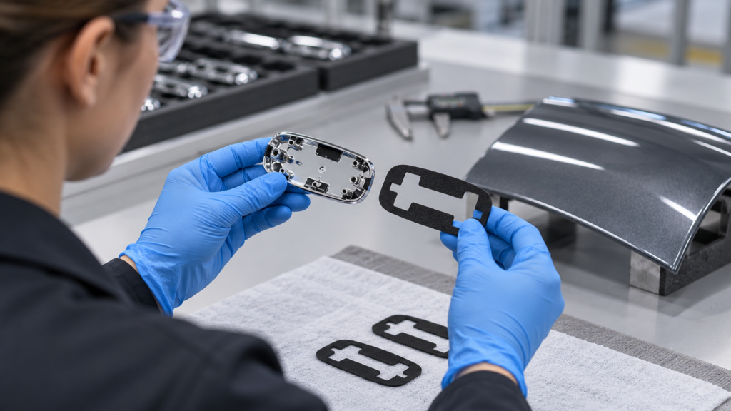
What evidence must be established before approving die-cut tape for this emblem-to-painted-panel joint?
Identify and reproduce both exact surfaces and the production geometry/process, then pass OEM-defined appearance and service tests on the proposed construction; broad family labels and competitor examples do not approve a specific joint.
This guide supports preliminary B2B qualification. tesa and 3M materials apply to their named products and systems only. No LubandArt grade is approved for a specific clearcoat, emblem substrate or vehicle program; final release requires representative samples and OEM-defined acceptance criteria.
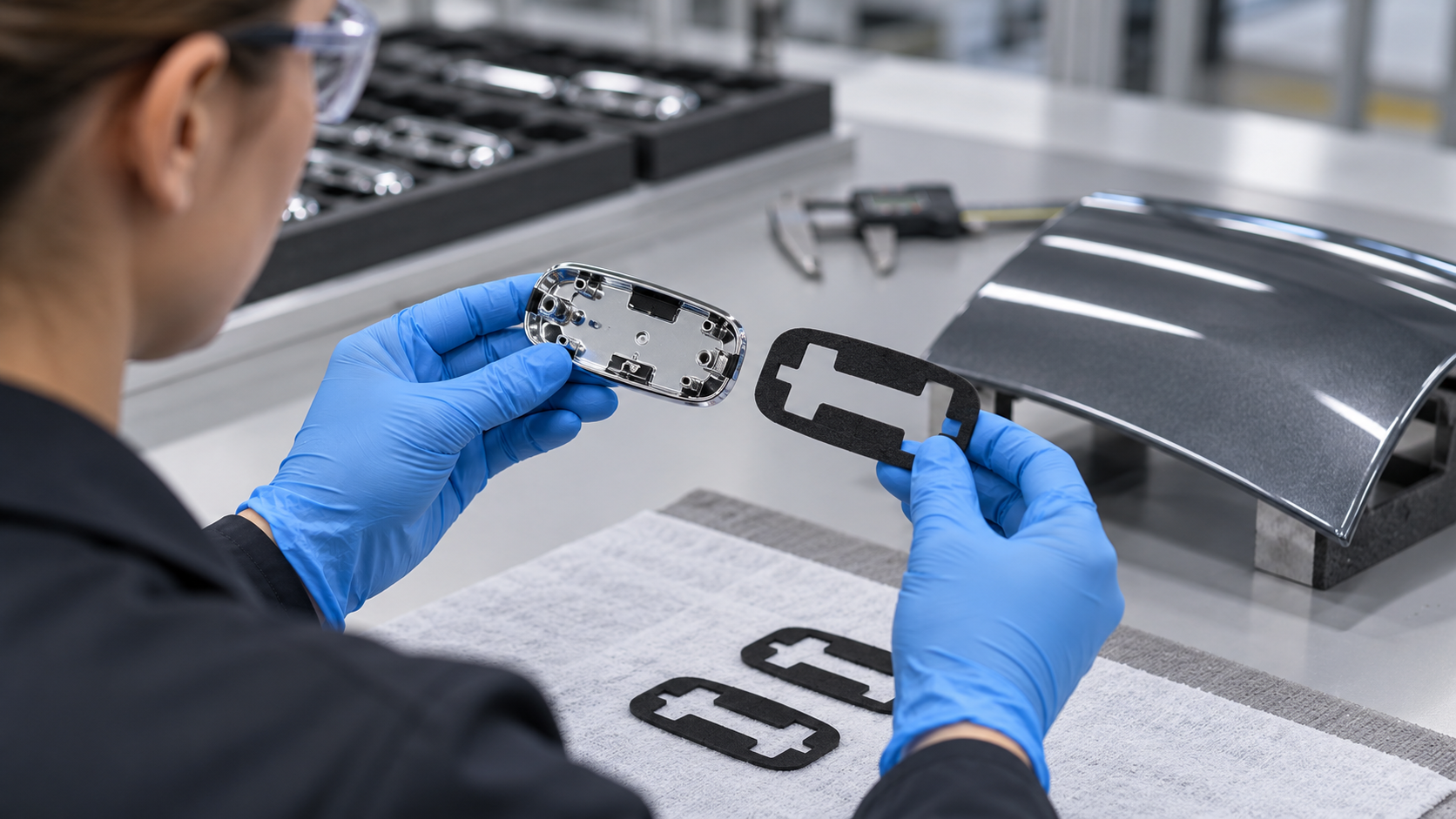
The decision is whether the exact emblem-to-panel joint can be released
For an automotive emblem or badge, a die-cut double-sided tape is a candidate only when the exact emblem backing, painted panel, bond geometry and application process are represented in qualification samples and pass the OEM’s appearance and durability criteria. For OEM teams evaluating die cut tape for automotive emblems, the release question is whether the exact joint passes the program criteria. A broad label such as “automotive acrylic foam” or a supplier’s emblem-mounting example does not establish compatibility with a particular clearcoat, chrome-plated plastic, emblem resin or vehicle program.
Identify and reproduce both exact surfaces and the production geometry/process, then pass OEM-defined appearance and service tests on the proposed construction before release. The practical release question is not simply which tape is strongest. It is whether the selected construction can hold the emblem flush and visually consistent without edge lift, rotation, adhesive exposure or paint damage over the specified service cycle. If the two bonding surfaces or acceptance limits are not known, keep the tape at candidate status and resolve those inputs before approving production tooling or a supplier part.
Identify the two actual bonding surfaces
Write down the precise surface on each side of the adhesive. On the vehicle side, “paint” could mean a particular basecoat/clearcoat system, a repaired area, a textured coating or another finish. On the emblem side, the tape may contact plated ABS, a coated polymer, painted metal or a molded back surface. The part material name alone does not describe the adhesive interface: coating chemistry, surface texture, mold release residue, cleaning, age and storage can all affect the sample.
Request the coating and emblem material revisions from the responsible OEM or Tier supplier. Record whether either surface is curved, ribbed, recessed or interrupted by locator features. Where a chrome-plated or low-surface-energy polymer is involved, do not assume a cleaning step or primer is interchangeable across materials. 3M’s application guidance treats substrate and surface preparation as application-specific; its procedures belong to the named 3M system and are not a universal instruction for another tape.
A useful first gate is therefore documentary: the drawing and bill of materials identify both bond surfaces, their finish, the allowed cleaning or priming process, and the revision level. If that information is missing, a coupon bonded to generic painted steel cannot close the gap.
Set geometry and appearance limits before choosing thickness
Small emblems can be more demanding than their area suggests. Thin letter strokes and narrow islands can concentrate peel or twist loads. A hidden lip may conceal the tape but also prevent contact. Curvature can leave a corner or edge under tension, and a thickness change can alter the emblem’s stand-off, reveal a dark bondline or create an uneven gap.
Map the tape footprint to the emblem back, including narrow strokes, islands, cutouts, carrier tabs and liner removal direction. Check the worst-case tolerance stack between the emblem back and painted panel, not only nominal CAD dimensions. Inspect whether the full intended tape land can be pressed uniformly without the emblem rocking on a locator or high point. The drawing should define visible gap, flushness, position, rotation and permitted tape exposure. Those are design acceptance limits, not properties a tape supplier can infer from a photo.
Select thickness only after those dimensions are known. A more conformable or thicker construction may help accommodate a defined gap, but it can also move the emblem outward, reduce flushness or increase edge leverage. Compare family-level roles in the PE foam versus acrylic foam guide, while keeping this article focused on the emblem assembly. A thin construction may improve a low-profile appearance but fail to contact an irregular surface. The correct thickness is the one that meets the joint geometry and performance requirements in the named assembly; no universal emblem thickness follows from the application category.
Make the die-cut and placement process part of the trial
A hand-applied strip is not a full production qualification for a die-cut badge. For liner and converting variables, see the tape converting liner selection guide. The sample should use the proposed tape construction, liner, cut geometry and placement sequence. Record lamination to the emblem, pressure method, tape and part temperature, liner removal, time between preparation and bonding, application pressure path and any fixture or locator. If the emblem is placed by robot or jig, use that equipment or a representative process window.
Keep separate trials for tape-to-emblem lamination and emblem-to-panel assembly when the operations differ. The 3M application guidance notes substrate-specific preparation exceptions for its systems; do not copy those procedures as universal instructions. The first can reveal poor converting, liner release, adhesive squeeze-out or tape displacement on a small feature. The second evaluates the final joint, including whether pressure reaches the complete footprint and whether the emblem sits correctly on the body surface. Avoid touching exposed adhesive, and control contamination and storage in line with the selected product’s instructions.
Use a controlled comparison when screening constructions: hold the substrates, cleaning, geometry and application method constant, and change one candidate variable at a time. Otherwise a better result may come from a different surface condition rather than the tape. Define inspection timing as well; pressure-sensitive bonds can develop over time, so an immediate handling check and an aged acceptance test answer different questions.
Qualify the service risks the vehicle program actually specifies
tesa identifies emblem mounting as an exterior application where contour fit and service exposure matter. Its emblem mounting overview is an application reference, not approval for another supplier. The tesa 62708 and 3M 06378 are named product examples with their own scope.
Build the test plan from the vehicle location and buyer requirements. Consider the relevant temperature range and cycling, moisture, UV exposure, wash chemicals, vibration, impact, and any assembly or paint-shop heat exposure. Not every emblem sees every condition, so avoid adding a generic test list without confirming the program profile. Use the OEM’s required methods, sample counts, conditioning periods and acceptance limits.
Inspect both function and appearance before and after conditioning. Record edge lift, shift, rotation, bondline visibility, cracking, adhesive transfer, paint change and the failure location. If retention is measured, specify the load direction and fixture: a peel result on a flat coupon is not the same as torque or edge loading on a small curved emblem. If removal or repair is relevant, document how the emblem is removed and whether the paint finish remains acceptable; do not infer repairability from a successful initial bond.
Keep supplier values and OEM release criteria separate. tesa describes emblem mounting as an exterior application where contour fit, visibility and environmental exposure matter, and publishes examples for its own named ranges. 3M also offers named automotive attachment products and application documents. These sources help identify design variables; their approvals, dimensions, preparation steps and performance data do not transfer to a LubandArt candidate.
What the buyer should require before release
Name the exact clearcoat/paint and emblem-back material/coating revision, condition, cleaning and permitted treatment. Overlay the tape shape on the emblem drawing and check worst-case gap, narrow strokes, curvature, locator interference, edge loading, flushness and tape exposure. Use representative painted panels, emblem parts, die-cuts and application equipment; test only the specified service exposures and inspect movement, edge lift, bondline, paint and failure location against OEM limits.
A production approval package should identify the exact tape grade and construction, die-cut drawing and revision, emblem and painted-panel revisions, preparation method, application equipment and controlled process window. It should connect each service requirement to a representative test and pass/fail criterion. The approved sample must reproduce the intended bond footprint and appearance, and the supplier should be able to maintain the agreed material, converting and traceability controls for repeat lots.
LubandArt’s acrylic foam tape product page supports a project discussion about configurable adhesive, thickness, color and die-cut formats. LubandArt publishes an acrylic foam family route and die-cut project options. The public information does not approve a specific grade for a named clearcoat, emblem resin or OEM program. Before treating it as a production solution, provide the two surface descriptions, drawing, tolerance stack, environmental profile, line sequence and acceptance criteria so a candidate and sample plan can be assessed.
If the project cannot disclose a named coating or emblem resin, use representative material samples with revision and supplier identification. If the OEM requires a specific qualification or appearance standard, include it rather than substituting a generic peel target. Release should be limited to the tested material pair, geometry and process window; changing the clearcoat, emblem back, die-cut footprint or application line may require requalification. Ads volume is an opportunity proxy and exact GSC/inquiry signals are absent in the reviewed period.
Frequently Asked Questions
Will any acrylic foam tape bond every automotive emblem to every clearcoat?
No. Compatibility depends on the exact clearcoat, emblem backing, surface condition, geometry and process. A named construction must be tested on the specified material pair.
Can I copy the thickness or application values from a tesa or 3M emblem product?
Use those sources only for their named products and conditions. Their values, approvals and process settings are not LubandArt specifications or universal limits.
What information is needed to assess an emblem tape sample?
Provide clearcoat and emblem-back revisions, a joint drawing with the die-cut footprint and tolerance stack, placement process, service profile, appearance limits and OEM pass/fail methods.
Send the paint and emblem-back revisions, die-cut drawing, tolerance stack, application sequence, service profile and OEM acceptance limits to scope a candidate/sample trial.
Request a quote · [email protected] · WhatsApp +86 180 6469 2463
Need this construction for a production run?
Get a quote