
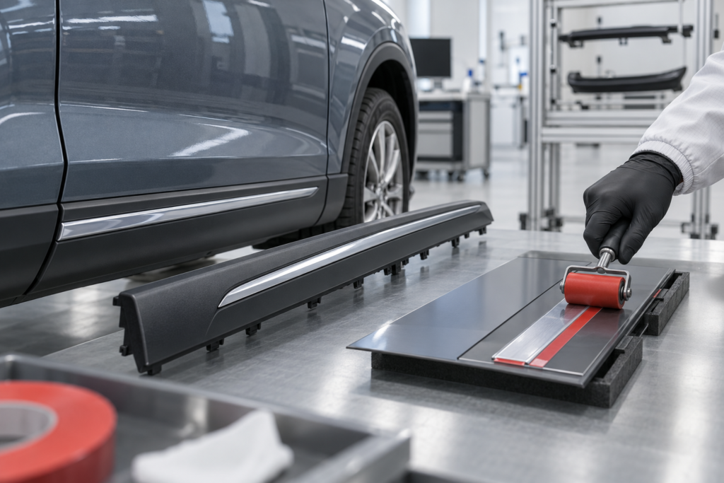
When evaluating automotive acrylic foam tape for an exterior trim-to-body joint, do not choose it from the keyword or nominal thickness alone. First verify the actual painted body surface and trim polymer, then design enough continuous tape land and clearance for the tape to contact both parts without the trim lip or feature line blocking it. Validate lamination, placement, pressure and wet-out on production-representative parts. LubandArt lists customizable acrylic foam tape for automotive exterior applications, but its product page does not publish a grade-specific release limit for a given paint-and-trim pair; suitability still depends on the proposed construction and the buyer’s sample test.
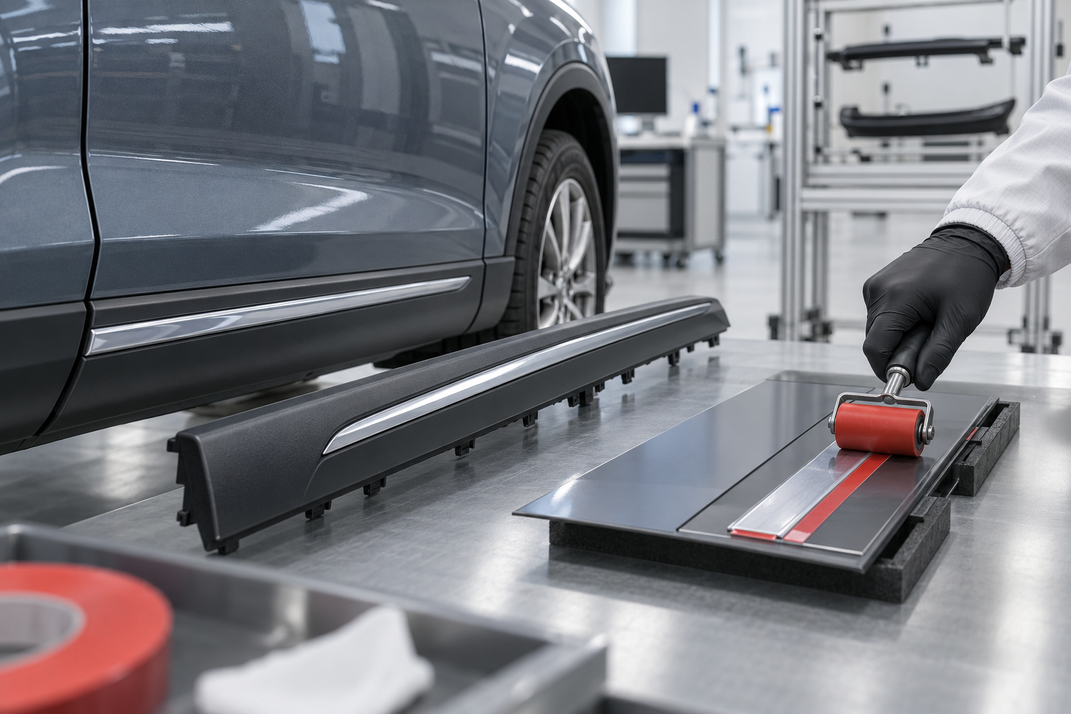
An exterior trim joint is partly a tape choice and partly a part-design and line-control problem. A narrow bond land, a recessed paint feature, variable trim stiffness or inconsistent pressurization can prevent full contact even when the adhesive family sounds appropriate. The useful engineering question is therefore: what must the part and process allow before a tape trial can give a meaningful result?
Start with both bonding surfaces and the load path
Write down the exact surface on each side of the joint. “Painted panel” is not enough: identify the coating system and finish, part location, cure history, and any wax, release agent or contamination that could affect the adhesive. On the trim side, record the polymer or composite, texture, curvature, molded features and any local coating. The adhesive contacts the outermost surface, which may be paint, a coating or a skin—not the base metal or resin named on a drawing.
Map the loads before selecting a construction. Note whether the trim is loaded mainly in shear, whether an edge can be peeled by airflow or handling, and whether the geometry creates a lever arm that pries the bond line. Record the part’s service environment and required appearance. A flush emblem, a long body-side molding and a flexible wheel-arch part do not create the same joint, even if each is called automotive exterior trim.
LubandArt’s acrylic foam tape product page describes a customizable acrylic foam carrier for automotive exterior parts and states that substrate suitability is confirmed against the project specification and sample test. That supports discussing a candidate route; it does not establish a particular peel value, temperature limit or vehicle-program approval. Ask for the exact proposed grade and its applicable technical documents before turning a product-family description into a drawing requirement.
Check the tape land, lip and tolerance stack
The tape must have a continuous, usable area where it can touch the part and the vehicle surface. Check bond-land width, interruptions, holes, ribs, curvature and the location of clips or fasteners. A trim feature that hides the tape can also shield it from pressure or stop the adhesive from reaching the painted panel. Review the body-panel, trim, locator and assembly tolerances together; nominal CAD alignment does not show the worst-case contact condition.
The 3M application guidelines for its acrylic foam and Acrylic Plus exterior-trim systems treat part materials, tape land and clearances as design inputs. In one hider-lip example, the guide recommends that tape stand at least 0.5 mm (0.02 in) proud of the lip and shows 0.55 mm as a minimum tape thickness in that guide context. These are 3M-specific recommendations, not LubandArt specifications or universal automotive limits. Use them to understand why the lip-to-tape relationship matters, then set the requirement from the proposed construction, part geometry and validation results.
If the trim is curved, inspect whether the part springs away from the body between locator points. If the bond land narrows near an end, account for the edge where peel may begin. Where possible, use section views and tolerance extremes to confirm that the tape can be compressed by the intended assembly method without the part bottoming on a hard stop first.
Make the assembly process part of the design review
Separate tape lamination to the trim from final placement on the vehicle. They may use different equipment, surface preparation, pressure and timing. Define how the trim is cleaned, how the tape is aligned, when the liner is removed, what fixture locates the part and how pressure reaches the full bond land. A hand-pressed coupon can show whether two materials appear compatible, but it cannot reproduce a production roller, press, fixture or locator sequence unless those conditions are represented.
The 3M exterior-trim application guidelines describe checks for tape application, part placement, pressurization and wet-out. Their purpose is to guide evaluation and processing of the named 3M products. The transferable lesson is to measure whether the intended assembly creates contact over the bond area; the specific settings, tools and acceptance values should not be copied across brands or constructions. A low-pressure zone, trapped debris or a locator that tilts the part can leave a local weak area that a single average peel result may hide.
Record line speed, roller or press condition, pressure method, part temperature, time between tape application and assembly, and any dwell before handling. If the process uses primer or surface treatment, document the exact product, application window and drying conditions. Do not add a primer simply because the trim is polymeric: determine whether it is appropriate for the actual surface and proposed adhesive system, then validate the full sequence.
Build a trial that can reject the wrong design
Use production-representative paint, trim, tape construction and process equipment. Include tolerance extremes or parts that represent them, not only a carefully matched center-of-range sample. Before the trial, agree what counts as acceptable contact, visible edge lift, position shift, noise, cosmetic damage and failure after the required conditioning. If the assembly sees heat, moisture, vibration or repeated loading, choose conditioning and mechanical checks that reflect that service rather than relying on a room-temperature initial bond.
Inspect where and how the joint fails. A clean separation at the paint interface points to a different investigation than adhesive transfer, cohesive failure in the foam carrier, trim deformation or paint damage. Note whether failure begins at an edge, a gap, a narrow land or a discontinuity. Photograph the surface and record material lot, tape lot, application conditions and elapsed time. That turns “the tape failed” into evidence about the surface, geometry, process or construction.
A peel test can be useful when its geometry and conditioning match the decision, but a tape coupon result is not the same as an assembled trim joint. Do not use one peel number to claim resistance to every combination of peel, shear, temperature, vibration and aging. The 3M guide is a process reference for its products; ask for a test plan and grade-specific data for the construction under review, then run the vehicle-part validation required by the program.
Know when to compare another construction
Acrylic foam tape is a candidate when the joint calls for a conformable structural attachment and the proposed product route matches the substrates and service conditions. If the actual need is mainly cushioning, sealing or filling a larger uneven gap, compare the joint against the distinct role of PE foam tape described in the PE foam versus acrylic foam guide. That comparison is a construction-level starting point, not a substitute for the body-panel and trim trial.
For plastic trim, distinguish acrylic foam structural attachment from PE foam tape used in PP and PE trim applications. The latter guide addresses a different foam-based selection question and does not establish that an acrylic foam grade will bond to a particular TPO, PP/EPDM or painted part. Record the exact surface pair and use the relevant product-family discussion only to narrow what to trial.
Put the release criteria into the RFQ
Send the supplier a drawing with the tape land and hider-lip geometry, the body coating and trim material, the tolerance stack, expected loads, service environment and assembly sequence. State the required converted format, dimensional tolerance, annual volume and the tests that determine acceptance. Ask the supplier to identify the proposed grade, its limitations, available grade-specific data and a sample plan using the real materials.
A sound decision is not “acrylic foam tape works on automotive trim.” It is that a named construction passed an agreed validation on the specified painted panel and trim, using the intended geometry and line process. If the part design does not provide a clear bond land or repeatable pressure, resolve that condition before changing tape thickness or approving production.
Frequently Asked Questions
Will an acrylic foam tape bond every automotive paint and trim combination?
No. Paint chemistry, coating condition, trim polymer, texture, contamination, geometry and application process vary. Qualify the proposed grade on the actual surface pair.
Can I copy a tape thickness or clearance from a 3M exterior-trim guide?
Use the guide for its stated 3M systems and design context. Its figures are not LubandArt specifications or universal limits; confirm dimensions with the selected grade, part tolerances and validation.
Is a hand-applied sample enough to release a production joint?
Only if it reproduces the conditions that control the production bond. Include the relevant roller, press, fixture, locator, surface treatment and dwell, then verify representative parts.
Send the painted-panel and trim material details, joint cross-section and tolerance stack, target tape land, load/environment and line sequence to request a candidate construction and representative sample trial.
Request a quote · [email protected] · WhatsApp +86 180 6469 2463
Need this construction for a production run?
Get a quote